The user can modify the shape of any object, which is drawn on the
Work Area. You are allowed to modify object's shape using the Pointer
Tool (the ![]() icon on the Object's Toolbar).
icon on the Object's Toolbar).
To use the Pointer Tool for modifying object shape:
1. Choose the Pointer tool.
2. Select the object whose shape you wish to modify. When working with the Pointer Tool use the following rules:
Lines:
3. When you move the mouse over the end points of a line, the mouse cursor prompts you to "Modify" by changing its pointer to a small cross.
4. Click the left mouse button and drag the end point of the line. A temporary representation of the new line appears. Its color contrasts with the background. Check how the line is changed.
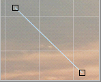
5. When you release the mouse button, the line takes on the new shape and looks like a spline. In the pictures below you can see the initial line (left) and the target spline (right), modified as described above in 4.
|
|
|
6. While dragging the mouse, you can press the ESC key or the right-click the mouse so as to stop the operation.
Note: Each spline vertex includes its own special points, which serve to round corners. When the spline vertex is selected, these points also become visible. You can drag these points as usual.
Polylines:
3. When you move the mouse over the vertex of a polyline, the mouse cursor prompts the user to "Modify" by changing its pointer to a small cross.
4. Click the left mouse button and drag the vertex. The temporary representation of the new polyline form appears; its color contrasts with the background. Check how the polyline has changed.
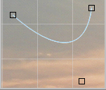
5. When you release the mouse button, the two segments of a polyline take on the new shape and look like a spline. In the pictures below you can see the initial polyline (left) and the target spline (right), which has been drawn using the rules discussed above in 4.
|
|
|
6. While dragging, you can press the ESC key or right-click the mouse in order to stop the operation.
Note: Each spline vertex includes its own special points, which serve to round corners. When the spline vertex is selected, these points also become visible. You can drag these points as usual.
Spline:
3. When you move the mouse over the vertex of the spline, the mouse cursor prompts you to "Modify" by changing its pointer to a small cross.
4. Hold the left mouse button down and drag the vertex. A temporary representation of a new spline form appears; its color contrasts with the background.
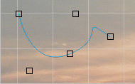
5. When you release the mouse button, the spline takes the new shape. In the pictures below you can see the initial spline (left) and the target spline (right), which has been drawn using the rules discussed above in 4.
|
|
|
6. You can press either the ESC key or right-click the mouse, while dragging the mouse, so as to stop the operation.
Note: Each spline vertex includes its own special points, which serve to round corners. When the spline vertex is selected, these points also become visible. You can drag these points as usual.
Rectangle:
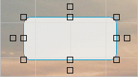
3. You can change the width and height of a rectangle by dragging any special point on the rectangle borders. All special points, which are placed outside of a rectangle, allow you to change its shape to a rhombus as shown on the pictures below. Here you can see the initial rectangle (left) and the target rhombus (right), which was drawn using the rules discussed above.
|
|
|
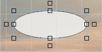
Ellipse:
3. You can change the width and height of an ellipse by dragging any special point on the ellipse borders. All special points, which are placed outside of an ellipse, allow you to change its shape to that of the other ellipse as shown on the pictures below. Here you can see the initial ellipse (left) and the target ellipse (right), which has been generated from the former by using the rules discussed above.
|
|
|
Note: You can also change the width and height of the object by entering new values into the General palette (or into the General tab in object properties).